Glade Reference
(Re)Initialises the floorplan.
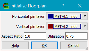
The Horizontal pin layer and Vertical pin layer fields set the layer for pins created on the top/bottom and left/right edges of the design boundary, respectively. Aspect ratio is the block aspect ratio, with numbers greater than 1 representing tall blocks and numbers less than 1 giving wide blocks. Utilisation is the desired cell utilisation, i.e. the ratio of total cell area to design boundary area.
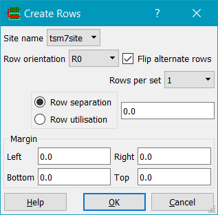
Creates rows for use with Place & Route. The design must have standard cells and a valid design boundary (a rectangle on the boundary layer). A valid Site name must exist, which will normally be found automatically from the library is a cell exists with the boolean property 'site'. Row orientation is the desired row orientation - R0, R180, MX and MY create horizontal rows wheras the rest create vertical rows. Flip alternate rows if checked will flip the orientation of adjacent rows to provide power track sharing in libraries that support it. Rows per set can be either 1 or 2 and specifies the number of rows placed together before any row spacing is applied. Row separation is the seperation between sets of rows, in microns. Altenatively Row utilisation can be give as a percentage. Margin specifies a margin around the rows, which are created inside the design boundary (boundary layer).
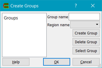
Creates and/or edits groups for use with Place & Route. Any existing groups are shown in the Groups list box on the left; clicking on a group in the list box updates the Group name field, and also the Region name field if there is a region associated with the group. Groups can be created using Create Group; instances must be selected first and a Group name must be specified (or be an existing group name). Delete Group will delete a group specified by the Group name. Select Group will select all instances of the group in the Group name field.
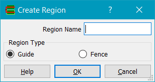
Creates a region for use with Place & Route. A region is a rectangle on the Region layer with string properties type and name. Regions can be of type Guide or Fence. Fence regions are hard constraints whereas Guide regions are soft constraints.
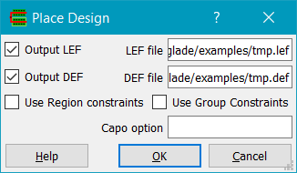
Places cells in rows using the UCLA Capo placer. Glade exports LEF and DEF from the current design and invokes Capo; on completion, Glade reads in the placed DEF.
The design must have rows for placement of cells, as defined using the Row layer, and a valid design area as defined by the boundary layer. Placement regions may exist as defined by the Region layer.
Currently only horizontal cell rows are supported for placement - this is a limitation of the Capo code. Rows can be flipped and cell orientations will obey row orientations (this is a bugfix from the distribution Capo code which assumes all rows are N orientation)
Unplaces all standard cells. Cells are moved to the right of the design area and have their orientation set to R0 and placement status set to unplaced.
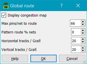
Runs global routing on the design. The design must be a placed standard cell or block design, imported using LEF/DEF or LEF/Verilog. Global routing partitions the design into bins also known as gcells. The size of the gcell has a direct impact on the speed and accuracy of the global routing: smaller gcells give a more accurate picture of the congestion but at the expense of speed. Max pins/net to route limits global routing to nets with less than the limit. Pattern route routes small two pin nets first using a L-shaped pattern. This is much faster than routing nets using the full maze router.
The congestion map displayed shows the gcell grid and the edge congestion in a colourmap. Edges that are blue have 0 more tracks available (supply) to route on than are required (demand). Cyan edges have a demand of 1, green edges have a demand of 2, yellow 3, red 4, purple 5, white greater than 5.
Currently the global router is single-layer i.e. all layers are compressed into one. This gives a good idea of congestion but no layer by layer congestion map. This is an area for future enhancement, as is accurately modelling obstructions.
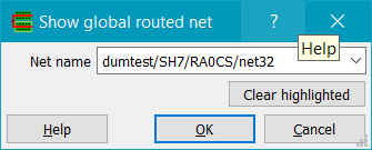
Displays the path the global router took for the user-specified net. If a net is not displayed, either it has more pins than the max pins/net limit, or the net starts and ends within the gcell.
Toggles the display of the congestion map.
Checks for any overlapping standard cells in the design, reporting their names and locations if found
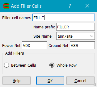
Adds filler cells. Rows must be present in order to add filler cells. The filler cells are specified by the filler name pattern given (e.g. FILL*). The instance names of fillers are prepended by the given name prefix and a count, e.g. FILLER1234. The site name needs to be specified from the list of site names. Power Net and Ground Net are the names of the power and ground nets that the filler cells should be connected to. Fillers can be added either for the whole row, or just between cells.
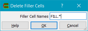
Deletes cells matching the pattern. Note that this can be used to delete any cells matching the pattern, not just filler cells.
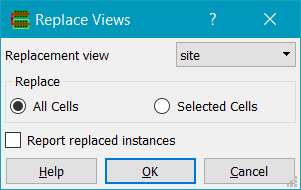
Replaces instances with masters of one view type with masters of another view type. Replacement view is the view to replace the existing master's view with. All Cells will replace all instances in the current cellview. Selected Cells will replaced just the instances in the selected set.
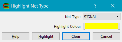
Highlights DEF nets by type i.e. SIGNAL, ANALOG, CLOCK, POWER, GROUND, RESET, SCAN, TIEOFF.
Copyright © Peardrop Design 2026.