Glade Reference
Zooms the display to fit the currently displayed cell's bounding box.
Zooms to 10% bigger than the displayed cell's bounding box.
Zooms in on the current cell by a factor of two. You can also zoom in by rotating the mouse wheel forward, or by pressing the right mouse button and dragging an area from lower left to upper right you want to zoom in to.
Zooms out on the current cell by a factor of two. You can also zoom out by rotating the mouse wheel backwards, or by pressing the right mouse button and dragging an area from upper right to lower left. The zoom factor is the current screen size divided by the drag rectangle size.
Zooms to fit the window around the selected set.
Moves the centre of the display to the entered point. Note that panning can also be achieved by dragging with the middle mouse button held down; the pan is done in real time.
Brings up a dialog box in which the X and Y coordinates to pan to can be entered. The display is then centered on these coordinates.
Redraws the screen. The display in Glade is double buffered, so redrawing consists of copying the back buffer to the front. This is fast, and in the OpenGL version of Glade is done using texture mapping which is accelerated by hardware when using modern graphics cards.. If however the display changes (e.g. by changing the layers that are visible in the LSW) then the back buffer has to be drawn again. However, this is still pretty fast.

Draws a ruler. Manhattan, 45 degree and all angle rulers are supported. The popup dialog (toggle using F3 bindkey) allows the ruler snap angle to be changed while entering the ruler. Checking the Invert text labelling box puts the major/minor ticks on the opposite side of the ruler to normal. This can be useful when measuring edges of shapes with dense fills where the ruler text is not easily visible. To more accurately measure distances between shapes, you can turn gravity on, then the start and end points of the ruler can snap to the shape edges. You can zoom and pan while drawing rulers.
Deletes all rulers in the cellview.
Sets the display levels to 0. No contents of cells are visible.
Sets the display levels to 99. Cells up to 99 levels of hierarchy will have their contents displayed.
Sets the viewport to the last view before a pan/zoom/fit etc.
Cancels the current redraw. This can be useful on very large designs.
Brings up the Display Preferences dialog.

Show Axes shows the X=0 and Y=0 axes.
Show Labels toggles the display of text labels. By default, text label display is turned off as in non-OpenGL display mode, drawing text labels can be slow if there are many labels.
Show Tracks displays the track grid for each layer for DEF based designs.
Display Path Centreline shows the centreline of path objects. Display Path Outline draws the outline of the path, based on its real width.
Display Origins - Labels shows the origin of text labels as a small cross. Display Origins - Instances shows the origin of instances as a small cross. Note that instance origins are only displayed if their bounding box is shown, i.e. they are at the display stop level.
Show Instance Names can be set to None, Master or Instance. With Master, the instance's master cell name is shown inside the instance bounding box. With Instance, the instance name is shown inside the instance bounding box.
Show Via Instance Names can be set to None or Master. This toggles the display of the via instance master.
Label Display allows finer control of text labels. Display Rotated Labels if checked displays text rotated as per its database orientation e.g. from GDS2. When unchecked, labels are displayed with no rotation (horizontally). Display top level labels only if checked will only display labels at the top of the cell hierarchy. Labels contained in lower levels will not be shown.
Label display scale factor will scale the displayed labels according to the scale factor set.
Transparent controls group selection. When checked, group members are selectable (and the group bounding box shape is not). When unchecked, group members are unselectable, but the group bounding box is. In non-transparent mode groups can be moved, copied, rotated etc. using the group layer shape.
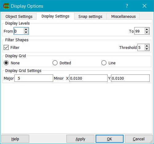
Display Levels sets the levels of hierarchy that are displayed. A display level of 0, for example, means only display shapes and instance bounding boxes in the current cell. Although the view level 99 command turns on viewing of 99 levels of hierarchy, there's really no limit.
Filter controls filtering of objects to speed redraw. When zoomed out, it makes no sense drawing objects that are so small that they contribute nothing to the visible display. So with filtering enabled, objects with a size smaller than the threshold (in pixels) are not drawn. Turning filtering off is the same as setting the threshold to 0. Note that path outlines are also subject to filtering; if the path width is less than the threshold then only the path centerline is drawn. Filtering can have a vast effect on redraw speed on large designs! The default filter level is 5 which is a good compromise of detail versus performance.
Display Grid controls the display grid which can be one of None, Dotted or Line.
Display Grid Settings. The Minor X and Y values set the dot or line spacing and are drawn using the 'mingrid' layer. The Major grid spacing is the number of minor grids per major grid dot or line; it should be an integer, typically 5 or 10. The major grid is drawn using the 'majgrid' layer.

Snap Grid controls cursor snapping. The cursor is snapped to the values specified in X and Y. Snapping is modified by gravity; see the Selection Options dialog.
Snap Angle controls the angle that data can be entered for some shape creation and also for rulers. Any allows all angles; 45 degrees and 90 degrees snap accordingly.

Infix Mode is used for commands which can take the current mouse position rather than relying on the user to click on the first point of the command.
Repeat commands will keep repeating a command until the ESC key is pressed.
Display coordinates in database units shows coordinates in DB units, rather than microns. This can be useful when working with e.g. DEF files where the ascii coordinates in the file are in DB units.
Always popup option dialogs when checked will always show option dialogs for dialogs such as Create Path. These option dialogs can be shown and hidden by toggling the F3 key. If Always popup option dialogs is not checked, then the option forms will not be shown automatically (but can still be shown by pressing F3). This is useful when entering e.g. a lot of polygons.
Immediate move/stretch of selected objects will let selected objects be moved by the cursor without issuing a move/select command. The cursor changes according to the object. To use, select an object in full mode, or an edge/vertex in partial mode. The cursor will change to a 4-way arrow (for full mode select) or a 2-way arrow (for partial mode select). Then left click and drag to move or stretch the object. The object is deselected afterwards (unless Keep immediate move selected is checked), so to repeat the command, select another object.
Keep immediate move selected will keep objects selected after an immediate move/stretch; otherwise all objects will be deselected.
Zoom centred on cursor will zoom around the cursor, rather than zooming the viewport.
Auto focus sets input focus to the canvas whenever the mouse moves over it. If this option is unchecked, then the user has to explicitly click on the main window in order to e.g. use bindkeys after any operation that transfers focus to another window. Some Window managers may override this operation because they provide control of focus directly.
Auto raise raises the canvas window the mouse is over automatically. If this option is not set, the canvas must be explicitly clicked on to make it the active window for accelerator key input.
Use True Layout Colour will use the layer colour/fill for drawing during Create/Move /Copy/Stretch commands, rather than a hollow fill in the cursor layer colour.
Draw Moving Inst Contents draws the contents of instances and vias while creating, moving or opying them. The contents are either shown with a hollow line fill in the cursor colour if Use true layer colour is not checked, or using the real layer colour and fill style if that option is checked.
Use Design Rule Halo will perform realtime DRC and highlight shapes that would give rise to DRC MINSPACE violations. The violating shapes have a halo drawn round them which is the MINSPACE distance away from their edges/vertices. Checking is done for shapes (not yet instances) that are created/moved/copied/stretched, against existing shapes either at the top level of the hierarchy or also lower levels. Hierarchy check depth is controlled by the display stop level, i.e. checking will be performed to the depth of hierarchy that is displayed. DRD options controls which rules are checked; Width if checked turns on width checking of shapes, using the MINWIDTH rule for the layer, Two layer spacing turns on spacing checks between two different layers, using two layer MINSPACE rules. Enclosure and Extension enable checking minimum enclosure/minimum extension rules using the techfile MINENC / MINEXT rules.
Halo Colour is the layer colour used to draw the DRC violation halo.
RMB mode sets the operation of the right mouse button. It can be set to Glade mode (dragging the mouse down zooms in, dragging it up zooms out), Virtuoso mode (dragging the right mouse in any direction zooms in) or Special mode (dragging the right mouse down zooms in, dragging it up left zooms out, dragging it up right does a window fit).
Displays the Selection Options form.
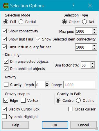
Selection Mode is set to Full or Partial. Bindkey F4 toggles between these modes. Full mode selects the entire object. Partial mode selects an edge or vertex of an object. Use Partial mode to select edges or vertices for subsequent stretch commands.
Selection Type can be either object mode or net mode. In object mode, only the object selected becomes part of the selected set. In net mode, if a selected object is part of a net then all shapes that are part of that net are selected.
Show connectivity displays flightlines between instance pins that have connectivity. Max pins sets the limit to the number of pins that a connectivity flightline is drawn. Show Inst Pins shows instance pins as well as nets when Show Connectivity or Show selected connectivity is checked. Show selected connectivity shows connectivity flightlines when an object is selected that has net connectivity.
Dim unselected objects will dim all unselected objects if any object(s) are selected. Unselected objects will be dimmed according to the Dim factor specified. This is useful when selecting an object e.g. a net by name in a large design and you want to display the selected object clearly. Dim unhilited objects will dim all unhighlighted objects, if highlighting is used e.g. by the Trace Net command.
Limit instPin query for net will limit the number of instance pins shown in the Query Net dialog. This is useful when querying power/ground nets which may have hundreds of thousands of special net pins. Such a number of pins means the dialog is slow to build. Regular net pins are always shown.
Gravity when enabled will snap the cursor box to the nearest shape edge or vertex. The Range field determines how far an object edge can be from the current cursor position for gravity to take effect. Gravity works for all shapes and also the bounding boxes of instances at the current level of hierarchy only. Depth sets how far down the physical hierarchy shapes will be snapped to; for example with depth=0 only shapes in the current cell will be snapped to. Note that the grid snapping as set in the display options dialog overrides gravity snapping: in other words gravity snapping will snap to the nearest coordinate on grid if an object's edge is not on grid.
Gravity snap to sets whether snapping to edges or vertices is carried out when gravity is on.
Gravity to Path sets whether gravity snaps to path centrelines or edges.
Display Cursor Box shows a small square box in the LSW cursor colour, centered on the cursor, which is snapped to the current snap grid, or snapped to the nearest edge within gravity distance if gravity is on.
Cross Cursor when checked will display the cursor as a crosshair rather than as a box.
Dynamic Highlight highlights the object that will be selected if the left mouse button is clicked in Full selection mode. In Edge selection mode it highlights selectable edges, and in Vertex selection mode it highlights selectable vertices.
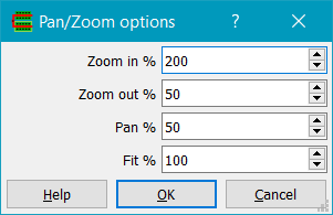
Displays the pan / zoom options dialog. Zoom in % sets the percentage that a zoom in changes the current magnification. For example 200% zooms in by a factor of two. Zoom out % sets the percentage that a zoom out changes the current magnification. For example 50% zooms out by a factor of two. Pan % sets the percentage of screen width that is panned by the pan keys (left/right/up/down keys). For example 50% means shift the viewport half of the current viewport width. Fit % sets the percentage of screen width occupied by the current cellview's bounding box when a Fit command is issued. It can be in the range 10%-100%.
Copyright © Peardrop Design 2026.