Glade Reference
Note that there are several function keys that can be used during viewing and editing. F1-F9 are hard coded and cannot be reassigned like bindkeys. On some platforms e.g. Mac, the function keys by default are assigned to special actions by the OS (for example raising/lowering the brightness of the display). It is possible to switch to normal Fn key mode operation (e.g. on the Mac by the Settings->Keyboard dialog).
Escape key - aborts the current command.
Return key - completes a Create Path, Create Polygon, Create MPP, Create Wire or Reshape command. The current cursor position is used as the last point. This is usuallly easier than double clicking to complete these commands.
Backspace key - deletes the last vertex during a Create Path, Create Polygon, Create MPP, Create Wire or Reshape command.
F1 key - opens the help browser.
F2 key - toggles the Selection Options 'Gravity Mode' on/off.
F3 key - shows/hides the command option dialogs.
F4 key - toggles the Selection Options Full and Partial selection modes.
F5 key - shows the Enter Coordinate dialog. For any command that normally takes a mouse click to enter a coordinate, F5 allows the user to specify the coordinates through the Enter Coordinates dialog box instead. For example, if you want to create a rectangle with coordinates (0.0, 0.0) (2.0, 3.0), click on the Create Rectangle icon, then press F5 and enter the first pair of coordinates and press OK. Then press F5 again and enter the second pair of coordinates.
F6 key - toggles the Selection Options 'Display Connectivity' mode on/off.
F7 key - toggles the Selection Options 'Selection Type' mode between Object and Net.
F8 key - toggles the Display Options 'Immediate Move' mode on/off.
F9 key - cycles through the Snap Mode angle.
Also note that double clicking the left mouse button will add a final path/mpp point, or add a final polygon point, or terminate the Reshape command.
undos the last edit made. Multiple undos can be carried out. Currently the only operations that can be undone are Delete, Move, Move Origin, Copy, Rotate, Stretch, Create, Merge, Chop, Flatten, Align, Reshape.
redos the last undo. Multiple redos can be carried out. Currently the only operations that can be redone are Delete, Move, Move Origin, Copy, Rotate, Stretch, Create, Merge, Chop, Flatten, Align, Reshape.
Copies the selected set into a yank buffer, for use with the Paste command.
Pastes the contents of the yank buffer into the current cellView.
deletes the current selected set. Deletes can be undone.
Copies the current selected set. The F3 key will toggle the Copy options dialog.
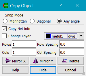
Snap Mode can be set to Manhattan, Diagonal or Any Angle. Copy Net info if checked will copy a shape's net connectivity. If a shape is being copied, Change Layer will allow the layer of the new shape to be changed. If Rows or Cols is set to a number greater than 1, an array of objects will be copied with the spacing set by Row Spacing and Col Spacing. If Mirror X is pressed (or the 'x' key) during a copy, the object is mirrored in the X axis. If Mirror Y is pressed (or the 'y' key) during a copy, the object is mirrored about the Y axis. If Rotate is pressed (or the 'r' key) the object is rotated 90 degrees anticlockwise.
If infix mode is on, the current cursor position is used for the reference coordinate. Else you will be prompted to enter the reference coordinate. During a copy operation, the object(s) are shown as outlines and delta coordinates (dX/dY) from the initial position are shown on the status bar.
Moves the current selected set. The F3 key will toggle the Move options dialog.
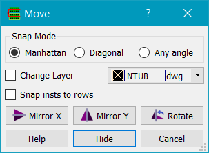
Snap Mode can be set to Manhattan, Diagonal or Any Angle. If a shape is being moved, Change Layer will allow its layer to be changed. If moving instances, Snap insts to rows will snap instances to row objects if they exist. If Mirror X is pressed (or the 'x' key) during a copy, the object is mirrored in the X axis. If Mirror Y is pressed (or the 'y' key) during a copy, the object is mirrored about the Y axis. If Rotate is pressed (or the 'r' key) the object is rotated 90 degrees anticlockwise.
If infix mode is on, the current cursor position is used for the reference coordinate. Else you will be prompted to enter the reference coordinate. During a move operation, the object(s) are shown as outlines and delta coordinates (dX/dY) from the initial position are shown on the status bar.
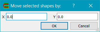
Move the current selected set by the distance specified in the Move By dialog.
Nudges the current selected set in small increments in X or Y.
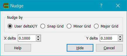
The distance to nudge by is set according to the Nudge By choice. User deltaX/Y takes the values of X delta and Y delta as the nudge distance. Snap Grid sets the nudge distance to the current X and Y snap distances. Minor Grid sets the nudge distnance to the current X and Y display grid. Major Grid sets the nudge distance to the minor display grid times the major grid multiplier.
After invoking the command, the left/right/up/down arrow keys moce the selected set according to the nudge distance, until the command is aborted by pressing the ESC key. While the nudge command is active, zooming, selecting/deselecting etc is available - but not panning via the arrow keys.
Stretches the current selected edge or vertex. The F3 key will toggle the Stretch options dialog.
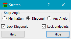
Snap Angle sets the allowed stretch direction. If objects as well as edges or vertices are selected, they are moved by the stretch distance. If Lock diagonals is checked, diagonal edges will be locked to 45 degrees. Otherwise moving an edge adjacent to a diagonal may make the diagonal edge become any angle. If Lock endpoints is checked, then stretching a path segment at the beginning or end of the path will split the path at the start or end vertex, keeping the start/end vertex fixed and stretching the other part of the split segment.
If infix mode is on, the current cursor position is used for the reference coordinate. Else you will be prompted to enter the reference coordinate. During a stretch operation, the object edge(s)/vertex(vertices) are shown as outlines and delta coordinates (dX/dY) from the initial position are shown on the status bar.
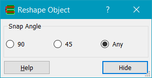
Reshapes the currently selected edge of a polygon or path. First select an edge of a polygon or the centreline of a path (in edge selection mode). Then enter vertices you wish to add to the edge. The original start and end points of the edge remain the same, vertices can be added with diagonal, manhattan or any angle snapping. Double click or press return to complete reshaping the edge. Pressing backspace will back up one vertex. Although Reshape only works with paths and polygons, you can convert any object e.g. a rectangle to a polygon using the Edit->Convert to Polygon command.
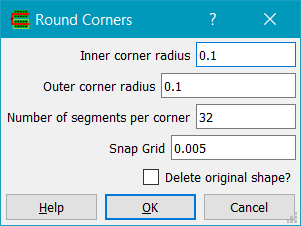
Rounds the corners of a rectangle or polygons. You must first select a shape to round. Corner radius sets the radius of curvature in microns. Number of segments per corner sets the precision of the generated curve which is made up of segments (straight lines). Snap Grid sets the manufacturing snap grid to avoid off-grid vertices; if no snapping is required set the value to the user database resolution (usually 0.001um). If Delete original shape is checked (the default), the original shape is deleted, else it is kept.
Adds a vertex to a selected path or polygon at the point given by the cursor. The vertex that has been added is selected so it can be moved using a Stretch command.
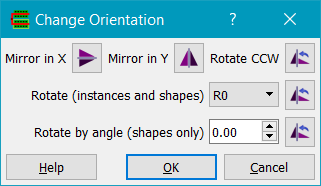
Rotates the current selected set about a point, which the user is prompted to enter. Mirror about Xaxis mirrors the objects in X, Mirror about Y axis mirrors the objects in Y. Rotate CCW rotates the objects counterclockwise. Rotate (instances and shapes) rotates instances according to the transform selected. Rotate by angle rotates shapes by any angle from -360.0 to +360.0 degrees; a positive angle corresponds to a clockwise rotation. Only shapes can be rotated by any angle; rectangles and squares get converted to polygons and are then rotated, while paths and polygons are maintained and their vertices are rotated. Note: cell placement orientation can be changed by querying the instance's properties and changing the orientation.
Moves the origin of the current cell. Click on the point that you want to make the new origin, and all object coordinates in the current cell will be changed to make this point (0, 0).
Converts selected shapes into polygons. Useful in conjunction with the Edit->Reshape command above.
Perform boolean operations on layers.
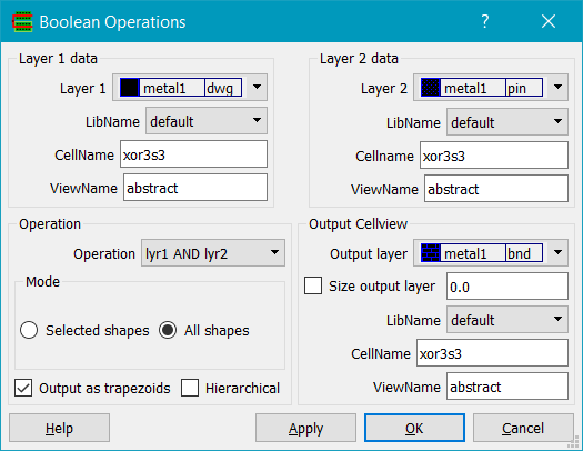
Layer1 and Layer2 are input layers, and Output Layer is the output layer. By default layer data is processed from the current open cellView, however it is possible to set the lib/cell/view names of the cells containing Layer1 data and Layer2 data.Operations that can be performed are two layer AND, two layer OR, single layer OR (merge), single layer NOT, two layer NOT, two layer XOR, sizing and up/down sizing (first size up by a given amount, then size down by the same amount - useful for removing small gaps or notches) and selection (select all shapes on a layer that touch shapes on another layer). Mode allows either selected shapes on Layer1 and, if used, Layer2 to be processed only, else all shapes for the layer(s) will be processed. If Output data as trapezoids is checked, the resulting layer is converted into trapezoids rather than complex polygons. If Hierarchical is checked, the design hierarchy is flattened and all shapes on the layer(s) are processed; else just shapes in the top level cellview are processed. The Output Cellview is the destination for the generated data. By default this is set to the current cellview, but can be any cellview; if the cellview does not exist it will be created. If Size Output Layer is checked, the output layer can be also sized by an amount (except for the operation Size lyr1).
Performs boolean operations on layers. Useful when the data is too large to process with Edit->Boolean Operations... as it uses a tiling algorithm to process the data tile by tile.
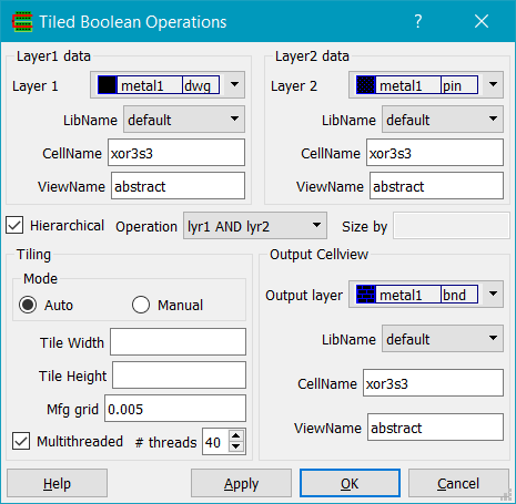
Layer1 data and Layer2 data specify the input layer sources. The cellView for each layer defaults to the current displayed cellView, but can be changed e.g. to compare two cells using an XOR operation on the same layer, for example. Operation specifies the boolean operation to be performed. Currently only merge (single layer OR), OR, AND, ANDNOT, NOT, XOR and SIZE operations are supported. The Output Cellview specifies the cellView that output shapes will be created on, according to the output layer specified.
If Hierarchical is checked, the cellView's data is flattenned before the operation.
Tile size can be determined automatically if Tiling Mode is set to Auto. Else the tile width and height can be specified if Tiling Mode is set to Manual. The larger the tile size, the more physical memory will be used. For large designs with many levels of hierarchy, computing the best tile size can take a long time - so in this case manually setting the tile sizes is preferable. Typically a starting point of 500-1000um should be acceptable. Seting smaller tile sizes will use less memory, but may run longer.
Multithreaded specifies that the tiles are split and run on a multiple number of threads, which may speed up overall runtime at the expense of somewhat more memory usage. # threads defaults to the maximum number of threads that are feasible on your system. For example, a 4 core Intel i7 processor will support 8 threads. Speed improvement is not linear with the number of threads due to IO and memory bottlenecks. Typically with 4 cores, about 3.5x speed improvement is gained.
Merges all selected shapes into polygons. Layers are preserved, i.e. only shapes on the same layer are merged. If you want to merge shapes on different layers, use the Edit->Booleans command with operation Layer1 OR layer2.
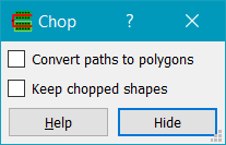
Chops a rectangle out of a selected shape. First, select a shape. Then invoke the chop command and draw a chop rectangle. The shape will have the rectangle chopped out of it. If Convert paths to polygons is checked, paths will be converted to polygons before the chop takes place. Otherwise paths will be maintained and will be cut. If Keep chopped shapes is checked, the chop shapes from polygons are not deleted.
Aligns objects and optionally spaces them in the direction perpendicular to the alignment edge.
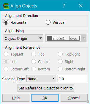
Alignment Direction is used when Align Using is set to Object Origin and can be horizontal or vertical. Horizontal will align objects horizontally e.g. by their left edges, and Vertical will align them vertically e.g. by their bottom edges.
Align Using can be by Object Origin, Object bBox or Layer bBox.
Spacing Type sets whether the objects should be spaced apart as they are aligned. It can be set to either None, Space or Pitch.
Click on Set Reference Object to align to to set the alignment reference object. Then click on the objects you wish to align; cancel or OK the dialog to finish an alignment sequence, or click again on Set Reference Object to start a new alignment. Note: cancel or OK the Align command before carrying out another command.
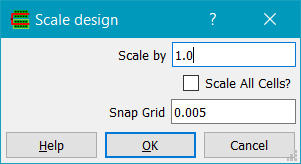
Scales all objects in the current cellview by a simple linear scale factor. If Scale all cells? is checked, all cells in the library will be scaled. Coordinates are snapped to the Snap Grid.
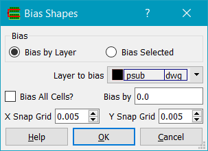
Bias can be either Bias by Layer, which biases all shapes on the specified Layer to bias, or Bias Selected (selected shapes can be on any layer). Bias by sets the bias. A positive bias causes shapes to grow in size; a negative bias causes them to shrink. If Bias all cells? is checked, all cells in the library will have the bias applied. Coordinates are snapped to the X Snap Grid and Y Snap Grid. Note that polygons with collinear or coincident points will not be biased correctly and a warning will be given.
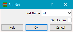
Sets the selected shape(s) net. The Net Name combo box is filled with any existing net names in the cellview, or you can type in a net name to create that net. If Pin? is checked, the shape(s) will become pin shapes.
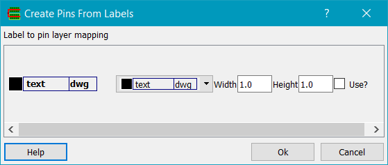
Creates pin shapes based on text labels. All label layers are shown in the dialog with a second layer chooser to allow control of the layer than pins will be generated on. Pins are created as rectangles centred on the label origin with the specified width and height. Pins are only created if the Use? option is checked.
Ascends one level of hierarchy, assuming you have previously descended into a cellview's hierarchy.
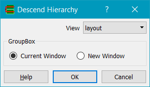
Descends down into the selected instance, or tries to find an instance under the cursor to descend into if nothing is selected. View is the view of the instance to descend into; for example a schematic instance may have both a symbol view and a schematic (lower level of hierarchy) view. Open In controls the window used to display the cellView; Current Window uses the existing window, and the Ascend command can be used to return to the previous cellView in the hierarchy. New Window opens a new window for the cellView, levaving the previous cellView window open.
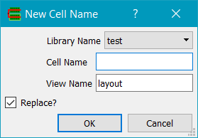
Library, Cell Name and View Name specify the new cellView to be created. By default the selected objects are deleted from the current cellView, and an instance of the new cellView is placed in the current cellView to replace them. If Replace? is checked, then the selected objects are deleted.
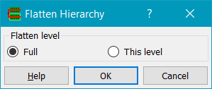
Flattens the current selected instances into the current cellView. Flatten level controls the flattening process; with Full checked the complete hierarchy from the current level down to leaf cells is flattened. If This Level is checked, then only instances at the current level of hierarchy are flattened; lower levels of the hierarchy are preserved.
Adds objects to an existing group. Add To Group prompts the user to select a group to add to, or uses an existing selected group. Then the user is prompted to select objects to add to the group. As objects are added, the group bounding box shape is modified to enclose the objects.
To create a group, use the Create->Group command.
Removes objects from a group. The group must be editable in transparent mode; use the View->Display Options dialog to set groups to transparent mode. Remove From Group prompts the user to selct objects, and removes them from the group. The group shape bounding box is adjusted to enclose the remaining shapes.
<
Ungroups objects. The Ungroup command prompts the user to select a group to ungroup, or uses an existing selected group.
Allows editing a cell in place. First select an instance that you want to edit. The Edit in place command will cause all subsequent selection and editing will be done in the master cell for that instance, but with the original top level cell displayed. The edit in place cell will be shown with layers of normal intensity, whereas all other shapes (of non-editable cells) will be shown dimmed.
Edit in place is hierarchical, i.e. you can choose to edit in place a cell within another cell you are currently editing in place.
Returns to the parent cell of the current edit in place cell.
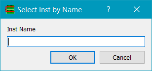
Displays the Select Inst dialog which allows selection of instances based on their instance name.
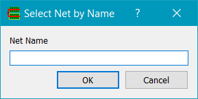
Displays the Select Net dialog which allows selection of nets based on their name.
Selects all currently selectable objects.
Deselects all the selected set.
Displays the Search dialog.
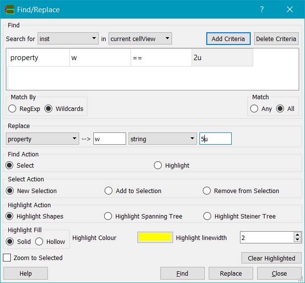
Find searches for objects, either in the current cellView, or hierarchically from the current cellView down, and optionally can replace them, or their attributes and/or properties. Names can be matched by Wildcards (e.g. VDD* matches VDD1, VDD2, VDD) or by RegExp (regular expressions). Currently you can search for instances, nets, shapes, ellipses/circles, labels, MPPs, paths, polygons, rectangles and viaInsts.
For each object type you can add a criteria. For example instances can have cell name, lib name, inst name, view name, orientation and properties as the criteria to match them. You can have one or more criteria, and match All criteria (i.e. the AND of each) or Any criteria (i.e. the OR of each).
Objects that match the search criteria can be added to the selected set or highlighted according to the Find Action. If Find Action is Select, objects will be selected, and further control is given by Select Action. New Selection clears any existing selected objects. Add to Selection adds the found selected ites to the selected set. Remove from Selection removes found objects from the selected set.
In the case of highlighted nets, they can be displayed either as the actual net shapes highlighted if Highlight Shapes is checked, or by a Spanning Tree between the instance pins of the instances the net connects to, or as a Steiner tree. This is useful, for example, in highlighting the connectivity of unrouted nets; the spanning tree is a good approximation to the path an autorouter will take; the Steiner tree is even better although can be slow on nets with many pins. The highlight colour can be chosen using the Highlight Colour button; the Highlight Fill can be Solid or Hollow and the linewidth can be specified for hollow fills. Optionally the display can Zoom to Selected object(s) and it is possible to clear all highlighted objects using the Clear highlighted button.
Once objects have been found (by clicking on the Find button), then it is possible to replace them. The Replace combo box shows the possible replacements depending on the object searched for. For example you can replace the layer of a shape, or the property of an object.
Note that it is not currently possible to undo the actions of the Replace command. Be sure to save first!
Queries the selected object. Note you can select and query an object by double clicking it with the left mouse button.
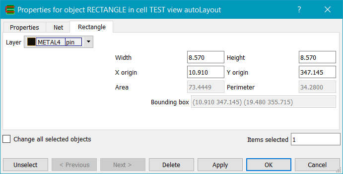
With nothing selected, the current cell's properties are queried. Otherwise you may query any selected object's properties and attributes, and cycle through the selected set using the Previous and Next buttons. You can delete a queried object using the Delete button. You can remove an object from the selected set with the Deselect button. If multiple objects are selected, Change all selected objects allows their common attributes to be changed. For example, if shapes are selected then the layer may be changed for all shapes. If the object has connectivity, a Net properties tab is added to the dialog. All objects may have user or system-defined properties which can be manipulated on the Properties tab page.
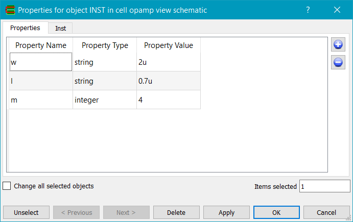
Properties can be added as string, float, integer, boolean, list or orient. Click on the property name or value to change the text, or click on the type and select the type in the combo box that will appear. Click on the '+' button to add a (initially blank) property entry, or select a property and click on the '-' button to delete the property. There is currently no undo capability if you delete a property!
All menus and toolbar buttons have actions. An action has a unique command associated with it; it also has an optional bindkey. For example the 'Open Cell' action by default has a bindkey Ctrl+O.
Bindkeys may be redefined by the user using the Edit Bindkeys command. This shows a table of all current bindkey assignments.
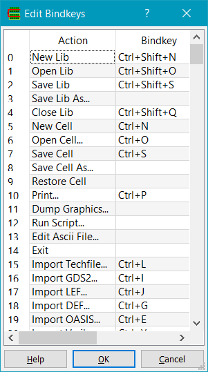
Clicking on the 'Bindkey' entry in the table allows editing the bindkey for that action. A single letter in uppercase indicates that key will be used. Modifier keys may be specified e.g. Shift+, Ctrl+, Alt+ and should precede the key, with no spaces.
Bindkeys are saved in the preferences file (~/.gladerc) and are loaded automatically every time Glade is run. A local .gladerc file will override values specified in the global ~/.gladerc file, so you have a project-specific subset of settings.
Copyright © Peardrop Design 2026.