Glade Reference
Create commands for shapes (text, paths, polygons and rectangles) all work on the current layer as set in the LSW by left mouse clicking on the layer box. All the create commands pop up a dialog box which can be shown or hidden by pressing the F3 bindkey. Create commands can be terminated by hitting the Escape bindkey. Zooming and panning is possible during Create commands.
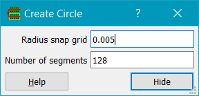
Creates a circle in the current cell on the current layer. Circles are entered using two left mouse clicks, or a single click if Infix mode is set. The first point (or the current cursor position if Infix mode is set) defines the centre of the circle, and the second point is a point on the circumference of the circle. Radius snap grid is the snap grid (usually the manufacturing grid) to snap the circle's radius to. Number of segments is the number of line segments used to represent the circle on export to GDS2 or OASIS.
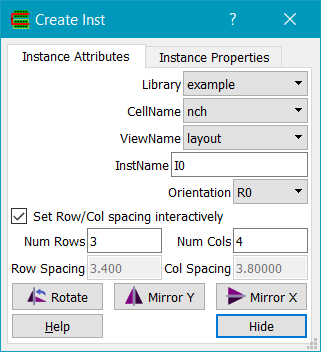
Creates an instance or array in the current cell. An instance is entered using a single left mouse click, which defines the origin of the instance. The instance master cell can be chosen from those present in the library using the cellName combo box and the viewName combo box. The instance's InstName is auto generated but can be changed by the user if required in the instName field. Orientation can be one of R0, R90, R180, R270, MX, MXR90, MY, MYR90. Arrays of instances can be generated if Num Rows and/or Num Cols is not 1; the spacing between rows and columns is set by Row Spacing and Column Spacing, unless Set Row/Col spacing interactively is checked. In that case, if Num Rows is greater than 1, the user is prompted for the location of the first instance of the second row (setting the rowSpacing), and if Num Cols is greater than 1, the user is prompted for the location of the first instance of the second column (setting the colSpacing). The instance bounding box is displayed during the command to assist in placement of the instance. Rotate (or the bindkey ‘r’ during instance placement) rotates the instance counter clockwise. Mirror Y (or the ‘y’ bindkey during instance placement) mirrors the instance about the Y axis. Mirror X (or the ‘x’ bindkey during instance placement) mirrors the instance about the X axis.
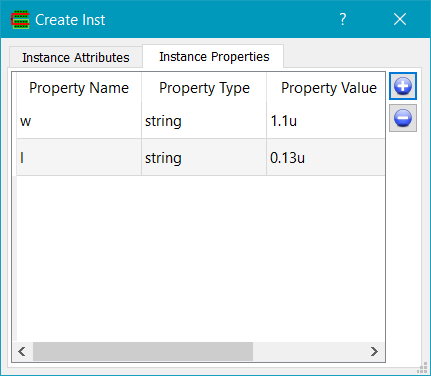
The Instance Properties tab can be used to set properties on the instance, e.g. if the master cell is a pcell or a symbol. The '+' button adds a property row. The Property Name column allows the property name to be edited. Clicking on the Property Type will display a combo box with the possible property types, e.g. string, integer, float etc. The Property Value column contains the property values.
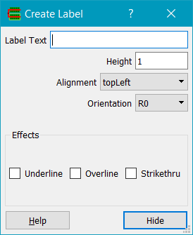
Creates a label in the current cell on the current layer with name given by the Label Text field. A label is entered using a single left mouse click, which defines the label's origin. Height defines the label's height. Presentation is the position of the origin relative to the text and can be one of topLeft, topCentre, topRight, centreLeft, centreCentre, centreRight, bottomLeft, bottomCentre or bottomRight. Orient can be one of R0, R90, R180, R270, MX, MXR90, MY, MYR90. Effects sets label effects such as Underline, Overline and Strikethru. Note that label effects, although displayed visually, cannot be represented in e.g. GDS2 or OASIS and so will be lost on export.
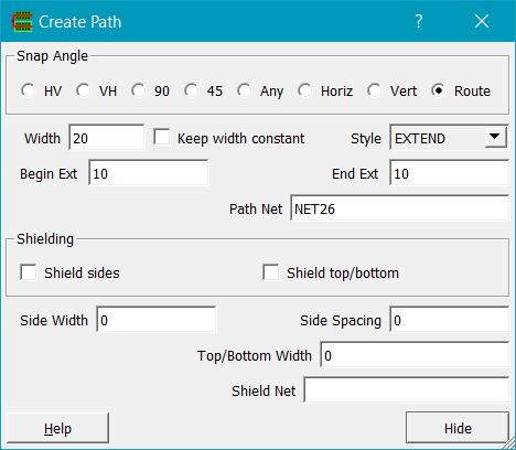
Creates a path in the current cell on the current layer. A path is entered using multiple left mouse clicks, with each click defining a path point. The path entry Snap Angle can be one of Any, 90 degrees or 45 degrees. The path width can be set in the Width field, and the path style can be set to one of Truncate, Octagon, Extend or VarExtend. In the case of Extend, the path extent is set to half the path width. In the case of VarExtend, independent beginning and ending extensions can be set. Path entry is terminated by hitting the return key, or by double clicking on the final point required. Pressing the backspace key backs up the path by one vertex i.e. deletes the last entered point. If an existing routed path is selected before invoking Create Path, the form is seeded with the path's net name and the layer of the existing path.
If the layer is a routing layer (has its FUNCTION set in the techfile to ROUTING) then the 'u' and 'd' keys can be used to switch up or down to the next routing layer during path entry. A via will be placed if a valid via between the two layers exists. If an existing net shape is selected, the Net and Layer fields are pre-seeded based on the net shape, and the Width field is set to that layer's minimum width.
Shield sides, if checked, results in shield paths generated to the sides of the entered path, in the same layer as the path. The width of the side shield paths is set by Side Width and the spacing from the shield to the path is set by Side Spacing. Shield top/bottom, if checked, results in shield paths on top of and below the entered path, with the bottom shield on the next routing layer below the path, and the top shield on the next routing layer above the path. The routing order is as set in the techfile by the layer FUNCTION statements - the the first layer with a FUNCTION of ROUTING is the lowest layer. The widths of the top and bottom shields are set by Top/Bottom Width. If Shield Net is set then the shields will be assigned to the net name specified; if it does not exist it will be created.

Creates a Multi Part Path (MPP). A MPP is defined in the techfile e.g. as below:
//
// MultiPartPath rules
//
MPP nguard LAYER nwell drawing WIDTH 1.80 BEGEXT 0.90 ENDEXT 0.9 ;
MPP nguard LAYER od drawing WIDTH 1.18 BEGEXT 0.59 ENDEXT 0.59 ;
MPP nguard LAYER nimp drawing WIDTH 1.54 BEGEXT 0.77 ENDEXT 0.77 ;
MPP nguard LAYER cont drawing WIDTH 0.16 BEGEXT -0.08 ENDEXT 0.08 SPACE 0.18 LENGTH 0.16 ;
MPP nguard LAYER metal1 drawing WIDTH 0.60 BEGEXT 0.30 ENDEXT 0.30 ;
A MPP is like a path in that it is defined as a set of vertices. A MPP may contain several layers. Each layer must have a nonzero WIDTH and a BEGEXT and ENDEXT which may be negative, positive or zero. The layer is justified to the segments of connected vertices i.e. it extends a half width either side of the path. The BEGEXT is the distance past the first vertex of the path that the layer starts, the ENDEXT is the distance past the last vertex of the path that the layer stops. If the layer has a SPACE and a LENGTH then it is assumed to be a repetitive contact structure, i.e. rectangles with WIDTH and LENGTH seperated by SPACE are generated.
Currently MPP paths must be manhattan only. MPPs when exported to GDS / OASIS etc. are converted to polygons i.e. they are flattenned.

Creates a polygon in the current cell on the current layer. A polygon is entered using multiple left mouse clicks, with each click defining a vertex of the polygon. The polygon entry snap angle can be one of Any, 90 degrees or 45 degrees. After two points have been entered, a dotted blue 'closure line' is shown. Hitting return at this stage completes the polygon according to the closure line. Polygons can also be finished by double clicking on a point. Pressing the backspace key backs up the polygon by one vertex i.e. deletes the last entered point.
Creates a rectangle in the current cell on the current layer. A rectangle is entered using two left mouse clicks, or a single click if Infix Mode is set. The first point (or the current cursor position if Infix mode is set) defines a vertex of the rectangle. A rubber band box is drawn showing the extent of the rectangle during mouse movement. Clicking on the second point completes the rectangle.

Creates a via in the current cell. Via Name is the name of an existing via in the library. Net is the name of the net that this via is assigned to.
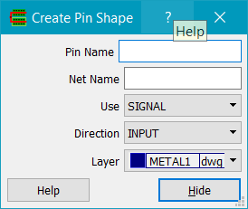
Creates a pin in the current cell. Pin Name is the name of the pin, Net Name is the name of the net that the pin belongs to. If the net does not exist it will be created. If an existing net shape is selected, Net Name is seeded with the selected net's name. Use determines the pin's type. Direction sets the pin's direction. The pin is created on the layer selected by the layer chooser field. Normally a pin purpose layer would be used.
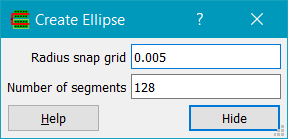
Creates an ellipse in the current cell on the current layer. Ellipses are entered using two left mouse clicks, or a single click if Infix mode is set. The first point (or the current cursor position if Infix mode is set) defines one corner of the ellipse's bounding box, and the second point defines the opposite corner of the ellipse's bounding box. Radius snap grid is the snap grid (usually the manufacturing grid) to snap the ellipse's bounding box to. Number of segments is the number of line segments used to represent the circle on export to GDS2 or OASIS.
Creates an arc in the current cell on the current layer. Arcs are entered using three left mouse clicks, or two clicks if Infix mode is set. The first click defines the centre of a circle that has the required arc on its circumference. The second click defines the radius of that circle, and the first point of the arc. The third click defines the span angle from the first point. The arc will be drawn clockwise or anticlockwise depending on the start angle and the stop angle. Note that arcs cannot be output to e.g. GDS2 or OASIS as they are line objects. They are intended for use with the symbol editor only.

Creates a group of objects. If a group is moved, all the objects within the group are moved. Similarly if a group is copied or rotated, all the object in the group are copied or rotated. Groups behave like pseudo instances, but without any physical hierarchy.
To create a group, either preselect objects; Create Group will create a group with name given by Name, and add the selected objects to the group. Or, if nothing is selected, the user is prompted to select objects to add to the group. Cancel or pressing ESC will cancel selecting objects to add. The group orientation is set by Orientation, and can subsequently be changed by selecting and querying the group.
Note that groups can contain other groups; a group cannot have itself as a member to avoid infinite recursion.
Groups are displayed as a rectangular shape on the group system layer, which is set to the bounding box of all the objects in the group. If the group's shape is selected it can be moved or copied.
To subsequently add or remove objects from a group, use the Edit->Add To Group or Edit->Remove From Group commands.
To ungroup objects, use the Edit->Ungroup command.
Groups can be transparent, in which case the group shape is not selectable but the objects in the group are, and can be moved independently. Transparency is set in the View->Display Options dialog. If transparency is disabled then individual group members are not selectable, only the group shape is.
Copyright © Peardrop Design 2026.