Glade Reference
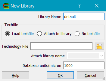
Creates a new library. Load techfile enables the Technology File field and will load that techfile into the new library. Attach to library enables the Attach library name field, and will attach the library's techfile to an existing (open) library. Database units/micron controls the precision of the represented data. Unless you have a good reason to change this and understand the implications, leave it as 1000 (i.e. 1 dbu = 1nm).
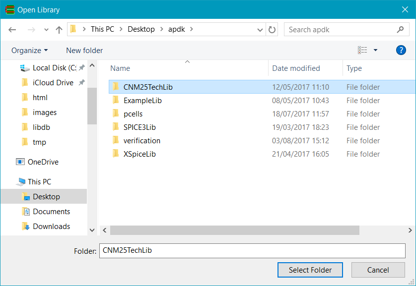
If you have an existing Glade library, you can use the Open Library command to specify a library name to open. Note that Glade libraries are just directories, so select the library by selecting the directory with the same name and click OK. Internally cellviews are stored as files of the form cellName/viewName. The library technology file is also stored in the library in binary format and is called glade.lib.
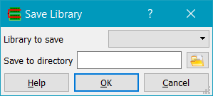
Use the File->Save Lib or File->Save Lib As... to save a library to disk after importing design data. You specify a library name, which translates to a directory name in Unix or Windows, and the library data is written to files in this directory. These files are binary - do not attempt to alter them, delete or rename them, or your design data may become corrupted.
<
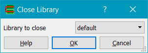
The Close Library command closes the chosen library. All cellviews from the library will be purged from virtual memory. The system will prompt you to save any modified cellviews. If a window displaying a cellView from the library is open, it will be closed.
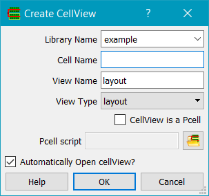
Use the New Cell dialog
to create a new cellview. The library given by Library Name must already exist. Specify
the Cell Name and the View Name. Set the View Type to the type of the
cellView; valid options are layout, schematic, symbol, abstract, autoLayout. Setting the View
Type will set a default View Name. If CellView is a PCell is checked, a
PCell (parameterised cell) will be read from the PCell script file. In this case the
Cell Name is automatically assigned from the python script name, and the Cell Name
field is greyed out.
The new cellView is added to the library and displayed in the library browser,
and automatically opened if Automatically Open cellView? Is checked.
Invokes the library browser to allow opening of a cellview.
Use the Save Cell command to save the current cellview to a library on disk.
Use the Restore Cell command to restore a cellview from disk.
Normally the sequence of importing design data into Glade is performed by importing a techfile first, then either importing GDS2 or importing LEF and then DEF. If you do not have a technology file, you can just import GDS2 or LEF/DEF, as basic technology information will be created for each layer read. In the case of GDS2, layers will be of the form L0, L1... where the number is the GDS2 layer number. All layers created by importing GDS2 will have purpose drawing, and layer colors will be assigned at random with hollow fill style. Layers created by importing LEF will have the LEF layer name and 4 purposes (drawing, net, pin and boundary). You can then subsequently export the technology file for later use.
Selecting File->Import->Skill Techfile... displays the Import Cadence Techfile dialog:
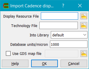
Display Resource File specifies the Cadence display resource file (typically display.drf). Technology File specifies the Cadence Skill technology file. Into Library should specify a library name to import the technology into, and will be created if it does not already exist. If the library does exist, the imported techfile will be merged with the existing one. This can produce unpredictable results and is not advised. Database units/micron sets the internal database resolution; in most cases 1000 is suitable. If Use GDS map file is set, stream layer/datatype numbers to Cadence layer/purpose names are set using a mapfile. The map file format is simply lines containing layer name, purpose name, stream layer number and stream datatype number. Comment lines (lines begininning with the # character) are ignored.
Note there are some limitations on importing Skill techfiles. Stipple patterns of size 4x4, 8x8, 16x16 and 32x32 are supported, other stipple pattern sizes will be rounded up to the next supported size. The Skill techfile should be written from Virtuoso and should not be hand edited else it may not parse sucessfully. However the parser can handle simple Skill expressions e.g. arithmetic operators, commonly found in techfiles.
Selecting File->Import->Laker Techfile displays the Import Laker techfile dialog:
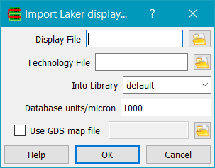
Display File specifies the Laker display file (typically default.dsp). Technology File specifies the Laker technology file. Into Library should specify a library name to import the technology into, and will be created if it does not already exist. If the library does exist, the imported techfile will be merged with the existing one. This can produce unpredictable results and is not advised. Database units/micron sets the database units. Use GDS map file, if checked, allows a GDS layermap file to be used. The map file format is simply lines containing layer name, purpose name, stream layer number and stream datatype number. Comment lines (lines begininning with the # character) are ignored. If the technology file also contains a tfStreamIoTable section, the map file entries will be merged and will overwrite tfStreamIoTable entries.
Laker stipple patterns of size 4x4, 8x8, 16x16 and 32x32 are supported, other stipple pattern sizes will be rounded up to the next supported size. Currently only layer colour / stipple / linestyle data and stream number / datatype info is read from the Laker techfile.
Selecting the File->Import->Techfile menu item displays the Import Techfile dialog.
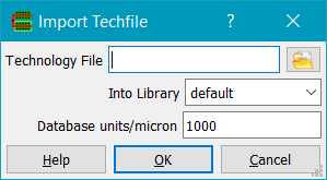
A (Glade) technology file can be used when no Cadence / Laker techfile is available. The Technology File can be chosen using the file chooser button. The Library name should be specified, and the library will be created if it does not already exist. If the library does exist, the imported techfile will be merged with the existing one. This can produce unpredictable results and is not advised. Database units/micron sets the internal database resolution; in most cases 1000 is suitable.
Selecting the File->Import->GDS2 menu item displays the Import GDS2 dialog:
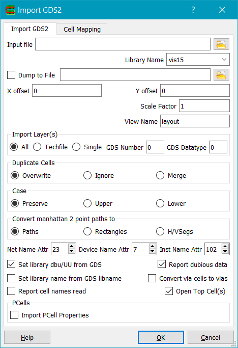
The GDS2 file to import can be chosen using the file chooser button. Multiple GDS2 files can be read if they are entered separated by a comma. If the file name extension is '.gz' then the compressed file will be unzipped on the fly. For debugging purposes, the GDS2 can be dumped to a readable ASCII format if the Dump to File button is checked and a file name given in the File name field.
The Library Name field specifies the library name that the GDS2 will be imported to. If you have previously read in a techfile, the library field will be preset to this library name. If the library does not exist, it will be created with a default techfile.
GDS2 can be scaled while read in if the Scale Factor field is set to a number other than 1. For example, if a scale factor of 0.5 is chosen, all coodinates will be multiplied by 0.5 and the design is shrunk by a factor of 2. This can be useful for scaling entire design databases.
An X offset and Y offset can also be specified. The specified offsets are added to all coordinates in the design, in effect moving the origin of the design. Note that offsets are applied BEFOREany user-specified Scale Factor.
The View Name specifies the view name created when a cell is imported. If cell mapping is used, this value will be overriden by the map library/cell/view names.
You have a choice of importing all layers, layers defined in the techfile or just a single layer in the Import Layer(s) field. When 'Single' is selected, a GDS2 layer number and datatype number need to be specified, and only shapes on this layer/datatype will be imported.
When cells are imported, if a cell of the same name exists you have 3 options available in the Duplicate Cells field. Overwrite means the new cell will replace the existing cell. Ignore will mean the new cell definition is ignored, along with all data in it. Merge means the original cell data is preserved, and any data in the new cell is added to it. This may cause duplicate shapes, but can be used to merge GDS data.
GDS2 structure and array names can have their Case preserved, forced to upper case or lower case depending on the 'Case' radio buttons. Note that if you have a structure named 'AND2' and one called 'and2' and do not preserve case, then the second structure encountered will give rise to a duplicate cell and will be handled by the settings in the Duplicate Cells field..
Manhattan 2 point paths can be converted to paths (the default), rectangles or H/V segs. The latter two can result is smaller memory usage (~5%) for designs that use lots of 2 point paths for e.g. metal fill or some P&R designs.
GDS2 properties can be used to import net names and instance names into the Glade database. Many layout editors and place & route tools can output this data, and if GDS2 properties are present with the chosen attribute numbers then net and/or instance names will be annotated into the database.
Set Library dbu/UU from GDS will set the library database units from that specified in the GDS2 file. This should normally be checked if importing into an empty library. If you want to import GDS2 data into an existing library, uncheck this so the existing library units can be used; the GDS2 data will be scaled to match if the GDS2 units differ from the library units. Note this scaling occurs before any user-defined offset or user-defined scale factor is applied.
Report Dubious Data will give warnings/errors to the message window if dubious data is encountered, such as polygons with less than 3 vertices.
Set library name from GDS libname will set the Glade library name of the imported GDs to the GDS library name.
Convert via cells to vias will identify potential via cells in the GDS. A via cell is a cell with 3 layers, of which two are of function ROUTING and one of function CUT, as defined in the techfile. A via will be created for each distinct cell and added to the library. On stream out via Export Gds2, vias can be converted back to cells. Note this option can increase import time of large GDS files.
Report cell names read will write each cell (GDS STRUCT) encountered in the input GDS data. For large designs this can slow things down so by default it is turned off.
Open Top Cell(s) will attempt to identify and open cells that appear to be the 'top cell' of a GDS file. A top cell is not referenced by other cells, and contains one of more cell placements.
if Import PCell Properties is checked, properties of PCells are imported if they have been written previously using the File->Export->GDS2 command with the option checked.
The GDS2 reader is single pass. As forward references are allowed in GDS2 (a cell, or GDS structure, can be referenced in a SREF before the cell has been defined), after reading the GDS a recursive check is made to ensure all cells have valid bounding boxes.
GDS2 structures are imported as cells with a view type of 'layout'.
GDS2 magnification is supported in Glade. GDS SREFs or AREFs (instances or arrays in Glade) can only have manhattan rotations. This is to maintain compatibility with Cadence Virtuoso , which has the same limitation.
GDS2 arrays are not allowed to have non-orthogonal row/column spacings. A warning is issued if encountered, and they will be represented as orthogonal arrays. This is consistent with Cadence Virtuoso and the GDS2 'specification'.
If a GDS file is imported without a Glade techfile having been previously read which defines the mapping between layer names/purposes and GDS layer numbers / datatypes, then the GDS layers are mapped to layer names e.g. L0 P0 for the first GDS layer/datatype shape encountered etc. The layer name assigned (L0) does NOT equate to the GDS layer number, it represents the first (internal) layer in the techfile. For this reason it is strongly recommended that you import GDS2 after importing a techfile containinglayer names and GDS layer/datatype mappings.
If a GDS file is imported into an existing library containing cellviews, any existing cellview of the same name as a GDS2 struct (cell) will be overwritten and a warning issued.
GDS2 cells (STRUCTs) can be mapped to cellViews using cell mapping tab:
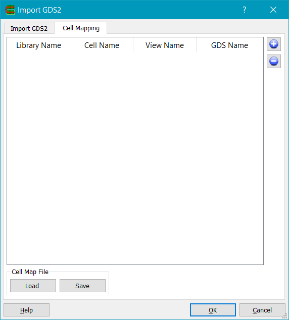
The + button adds an entry to the map table, the - button removed a selected entry. The GDS Name field specifies the GDS2 STRUCT name, and the Library Name, Cell Name and View Name specify the cellView to map this STRUCT to. The cell mapping can be loaded or saved to a file; the format is ascii and consists of 4 values per line (library name, cell name, view name and GDS name) separated by whitespace. The same format is used by the cell map table in the File->Export->GDS2 command.
Reference libraries to resolve SREF references can be defined in the reference libraries tab:

The + button adds a reference library entry whose name can then be typed in; the - button removed a selected reference library. The up and down arrow move the selected library up or down. When importing a GDS, cells (GDS STRUCTs) are checked to see if they exist in any of the the reference libraries, starting at the first. If a matching cell name is found, then the cell is not imported into the target library, and its reference will be to the cell in the reference library.
Selecting File->Import->OASIS displays the Import Oasis dialog:
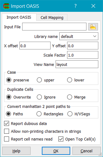
OASIS is a replacement for GDS2 with data compression to give much smaller file sizes. Typically 10-50x compression compared to GDS2 can be achieved. The OASIS reader supports CBLOCK compressed records and both strict and non-strict mode OASIS files.
The OASIS input file to be imported can be chosen using the file browser button. A library name to import the OASIS into MUST be specified, and will be created if it does not already exist. Multiple OASIS files can be read if they are entered separated by a comma, however subsequent OASIS files should not try and redefine cells previously defined or an error will result.
OASIS data can be scaled while read in if the Scale Factor field is set to a number other than 1. For example, if a scale factor of 0.5 is chosen, all coodinates will be multiplied by 0.5 and the design is shrunk by a factor of 2. This can be useful for scaling entire design databases.
An X offset and Y offset can also be specified. The specified offsets are added to all coordinates in the design, in effect moving the origin of the design. Note that offsets are applied BEFORE any user-specified Scale Factor.
The View Name specifies the view name created when a cell is imported. If cell mapping is used, this value will be overriden by the map library/cell/view names.
OASIS structure and array names can have their Case preserved, forced to upper case or lower case depending on the 'Case' radio buttons. Note that if you have a structure named 'AND2' and one called 'and2' and do not preserve case, then the second structure encountered will give rise to a duplicate cell and will be handled by the settings in the Duplicate Cells field..
When cells are imported, if a cell of the same name exists you have 3 options available in the Duplicate Cells field. Overwrite means the new cell will replace the existing cell. Ignore will mean the new cell definition is ignored, along with all data in it. Merge means the original cell data is preserved, and any data in the new cell is added to it. This may cause duplicate shapes, but can be used to merge GDS data.
Manhattan 2 point paths can be converted to paths (the default), rectangles or H/V segs. The latter two can result is smaller memory usage (~5%) for designs that use lots of 2 point paths for e.g. metal fill or some P&R designs.
OASIS properties can be used to import net names and instance names into the Glade database. Many layout editors and place & route tools can output this data, and if OASIS properties are present with the chosen attribute numbers then net and/or instance names will be annotated into the database.
If Report dubious data is checked, errors are reported for e.g. polygons with less than 3 vertices. If Allow non-printing characters in strings is checked, then any valid ascii character is allowed in e.g. text names; else only printing characters as defined in the Oasis spec are allowed.
At present the following OASIS constructs are silently ignored:
If an OASIS file is imported into an existing library containing cellviews, any existing cellview of the same name as a OASIS cell will be overwritten and a warning issued.
OASIS cells can be mapped to cellViews using cell mapping tab:
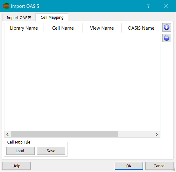
The + button adds an entry to the map table, the - button removed a selected entry. The OASIS Name field specifies the OASIS cellname, and the Library Name, Cell Name and View Name specify the cellView to map this name to. The cell mapping can be loaded or saved to a file; the format is ascii and consists of 4 values per line (library name, cell name, view name and OASIS name) separated by whitespace. The same format is used by the cell map table in the File->Export->OASIS command.
Selecting the File->Import->LEF menu item displays the Import LEF dialog:
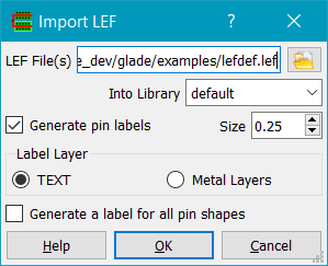
The LEF file(s) to be imported can be chosen using the file browser button. Multiple LEF files may be read by selecting each one in the file browser, or if they are entered separated by a comma. If the file name extension is '.gz' then the compressed file will be unzipped on the fly. A library to import the LEF into should be specified, and will be created if it does not already exist. Multiple LEF files can be read, however subsequent LEF files should not try and redefine sites or macros previously defined or an error will result. A technology LEF should always be read first - this contains layer definitions for routing and cut layers. Note that all LEF files should have a VERSION statement to be valid LEF files.
If the LEF UNITS are larger than the database units (by default 1000 dbu/micron) e.g. 2000, then the library database units are changed to the LEF UNITS. For this reason one should ensure that the first LEF file read has the largest UNITS.
LEF Macros are imported as cells with a view type of 'abstract'. A rectangle on the system layer 'boundary' is created for each macro according to the macro's SIZE . LEF OBS statements create shapes on the 'boundary' purpose for that shape, and LEF PORT statements create shapes on the 'pin' purpose. If the Generate pin labels option is set, text labels are created for the LEF pins on the system Text layer and can be displayed by making labels visible - see the Display Options command. Size sets the size of the generated labels. The labels are generated on a layer as specified by the Label Layer field; either the system layer TEXT purpose drawing or the same layer as the pin shape, but with purpose 'TXT'. If Generate a label for all pin shapes is checked, multiple labels will be generated for each pin shape. This is not desirable for standard cells, but can be useful for large macros.
If a LEF file is imported into an existing library containing cellviews, any existing cellview of the same name as a LEF macro and view 'abstract' will NOT be overwritten.
Selecting the File->Import->DEF menu item displays the Import DEF dialog:
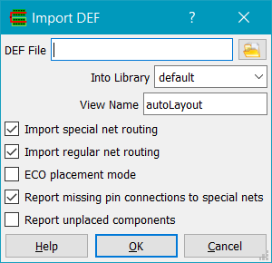
The DEF File to be imported can be chosen with the file browser button. If the file name extension is '.gz' then the compressed file will be unzipped on the fly. A library to import the DEF into MUST be specified in the Into Library> field and will be created if it does not already exist.
LEF must have previously been imported to create abstract views for all components defined in the DEF COMPONENTS section; however you can set the View Name to 'abstract' when importing DEF to create an abstract for use by other DEF files, for example for a hierarchical design.
View List specifies the view list that is searched for each DEF component. A master cellView with the component name and the first valid view in the list will be chosen. A rectangle on the system layer 'boundary' is created according to the DEF DIEAREA statement.
If the ECO placement mode button is checked, the DIAREA secion of the DEF is updated, the COMPONENTS section of the DEF file will be parsed and instance origins and orientations of the current cellview will be updated, and the PINS section of the DEF will be parsed, replacing existing pins. All components in the ECO file must exist in the current open cellview.
If Additional DEF pin layer is checked, a DEF PIN has and additional shape on the same routing layer but with purpose given by Purpose. This is in addition to the normal 'pin' purpose shape.
DEF PINs have pin text labels on either the system 'text' layer or on the routing layer according to the setting of the Pin Label Layer.
Report Missing pin connections to special nets will report all missing pin connections to special nets. Sometimes you don't care and this option can be turned off to minimise verbosity. Report Unplaced components report DEF COMPONENTS that do not have status PLACED.
If Import special net routing is checked, special net routing will be created in the design. If it is not checked only the connectivity information is imported.
If Import regular net routing is checked, regular net routing will be created in the design. If it is not checked only connectivity information is imported.
Import DEF will expect all referenced macros to have been previously imported by the Import LEF command as abstract views. Macros can be either imported into the same library as the DEF, or in multiple libraries, in which case Import DEF will search the libraries to resolve instance masters. However there is a restriction in that DEF must be imported into a library that has had a technology LEF imported (this is so the library has layer information such as layer type of routing, cut etc. defined). Failure to do so will give rise to via layers not being correctly recognised.
If you are importing hierarchical DEFs, you need to import the child cell DEF files first and set the View Name to abstract. You should also import each child DEF into a unique library, which has its technology file and technology LEF already imported. The reason is that P&R tools create DEF viaRule vias with names that may not be unique between different DEF files (e.g. a typical viaRule via called M1M2GEN may have variants M1M2GEN_1, M1M2GEN_2 etc. created). So if you try and import multiple DEFs into a single library, you will most likely get duplicate via name warnings, and only the viaRule vias of the first DEF file will be used.
So for example a section of Python code to load sub block DEFs and a top level def could be:
from ui import *
gui = cvar.uiptr
gui.importTech("lib1", "my.tch")
gui.importLef("lib1", "tech.lef")gui.importLef("lib1", "stdcells.lef")
gui.importTech("lib2", "my.tch")
gui.importLef("lib2", "tech.lef")
gui.importDef("lib2", "abstract", "block1.def")gui.importTech("lib3", "my.tch")
gui.importLef("lib3", "tech.lef")
gui.importDef("lib3", "abstract", "block2.def")# top level DEF
gui.importDef("lib1", "autoLayout", "top.def")
Note that if you import DEF which references multiple libraries created by importing LEF, all the LEF libraries must have the same LEF UNITS!
Import DEF creates a cellView with a cellname as defined by the DEF DESIGN keyword.
Selecting File->Import->Verilog menu item displays the Import Verilog dialog:
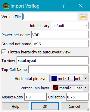
The verilog file to be imported can be chosen with the file browser button. A library to import the Verilog into MUST be specified, and will be created if it does not already exist. The power and ground net names will be used to connect any logic 1 (verilog 1'b1) and logic 0 (verilog 1'b0) nets to. Verilog modules will be imported into the database as verilog views. Leaf cells must exist as abstract views (from Import LEF) for flattening to work. If Flatten hierarchy is checked, the top cell will be flattened into the view specified, and Verilog leaf cells mapped to LEF cells of the same name. During the flattening process, instance pins on leaf cells are connected to the power and ground nets of the same name. Pins are created for inputs and outputs of the top level module. The pins will be on the Horizontal pin layer for pins on the left and right of the block and on the Vertical pin layer for pins on the top and bottom of the block. Aspect ratio sets the aspect ration of the block; the number is the ratio of height to width. Utilisation sets the ratio of cell area to design boundary size. Rows are created in the design and cells are placed randomly in the rows, spaced by 2 times the site width.
Verilog modules are imported as cells with a view type of 'verilog'.
NB Only basic structural level Verilog is supported. Simple ASSIGN statements are supported.
Selecting File->Import->ECO displays the Import ECO dialog:
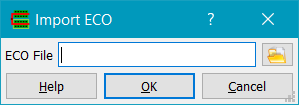
This is used for importing an ECO file to make changes to the connectivity of the current open design.
An example of ECO file syntax is as follows. Lines beginning with a '#' are comments.
- Detach Pin AF|AFFF|U179.B from Net AF|AFFF|N351 ;
- Delete Pin AF|AFFF|U179.B ;
- Detach Pin AF|AFFF|U179.A from Net AF|AFFF|N356 ;
- Delete Pin AF|AFFF|U179.A ;
- Detach Pin AF|AFFF|U179.Y from Net AF|AFFF|N368 ;
- Delete Pin AF|AFFF|U179.Y ;
- Change Cell AF|AFFF|U179 from Model NOR2X1 to Model NOR2X2 ;
- Add Pin AF|AFFF|U179.B ;
- Attach Pin AF|AFFF|U179.B from Net AF|AFFF|N351 ;
- Add Pin AF|AFFF|U179.A ;
- Attach Pin AF|AFFF|U179.A from Net AF|AFFF|N356 ;
- Add Pin AF|AFFF|U179.Y ;
- Attach Pin AF|AFFF|U179.Y from Net AF|AFFF|N368 ;
Selecting File->Import->DXF... displays the Import DXF dialog:
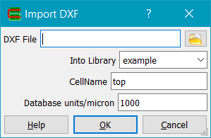
DXF is a common drafting format. DXF file specifies the name of the DXF file to import; the file can be chosen with the file browser button. A library must be specified; it will be created if it does not already exist. A cell name to import the drawing into must also be specified; it defaults to 'top'. Hierarchical designs can be imported.
Selecting File->Import->EDIF… displays the Import EDIF dialog.
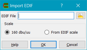
EDIF is a format for exchanging schematic and netlist data. EDIF File specifies the name of the EDIF file to import. Scale defines the resulting database units; 160dbu/uu is typical for Cadence compatible schematics. From EDIF scale sets the database units per user unit (dbu/uu) to that defined by the EDIF numberDefinition entry.
When exporting EDIF from another CAD system, symbol libraries should be exported as externals in EDIF. Then, when importing EDIF into Glade, matching libraries should be opened before the import. The Glade symbol libraries will obviously need to have the same size symbols, with the same pin names/locations as the originals. Alternatively it is possible to export symbol libraries in EDIF and have them created in Glade.
Although EDIF is supposed to be a ‘standard’, interpretation is another matter and how design data is exported is very much vendor-dependent.
The File->Import->DSPF… command displays the Import DSPF dialog.
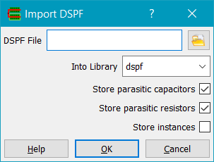
DSPF File specifies the name of the DSPF file to import.
Into Library specifies the library to import into.
Purpose Name specifies the layer prupose for nets to be created on, the default is 'net'.
Action> specifies what to do is a top level cell already exists for the DSPF being imported.
If Read All Nets? is checked, all DSPF nets will be read, else only those specified in the Net names to read field will be imported.
Store Parasitic Capacitors reads the C….. lines in the DSPF and creates parasitic capacitors and their subnodes.
Store Parasitic Resistors reads the R… lines in the DSPF and creates parasitic resistors and their subnodes. The rectangular resistor shapes (defined by their $X, $Y, $L, $W values, plus their subnode $X, $Y values) are created in the top level cell.
Store Instances generates instance masters and instances in the top level cell.
Glade currently permits exporting design data in GDS2, OASIS, LEF, DEF, DXF, Verilog and CDLformats.
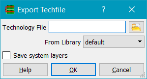
Choose a library to export the techfile from, and the name of an output file which can be selected by using the file chooser button. If Save system layers is checked, they will be written to the techfile. This is only necessary if you do not want to use the default layer colors e.g. if you want a white background, you need to set the 'backgnd' system layer color to white, and set the 'select' color to something other than white, and e.g. the 'cursor' color to something other than yellow etc.
Selecting the File->Export->GDS2 menu item displays the Export GDS2 dialog:
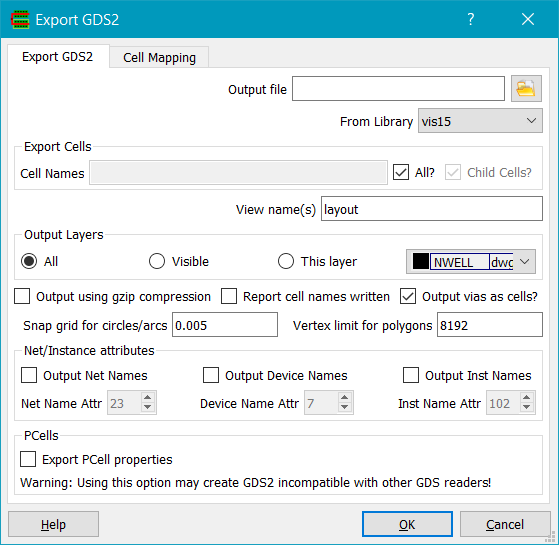
Choose a library to export GDS2 from, and the name of an output file which can be selected by using the file chooser button. If you want to output only certain cells in the design, specify them in the Export Cells Cell Names field and uncheck the All? button. Else if All? is checked then all cells in the library will be exported. If Child Cells is checked, then cells are exported to match the instances in the design hierarchy being exported.
The View name(s) field allows you to specify what views are exported. The view names can be delimited by whitespace. Note for example if you want to output from a LEF/DEF top level cellView, you will need to specify autoLayout (the view type of the DEF top level), abstract (the view type of the LEF cells) and layout (the view type of the vias). If your design contains cells with multiple views of viewType maskLayout, then this field is automatically populated with the view names.
Cells specified in the Export Cells field will be output with all subcells i.e. the complete hierarchy will be output, thus the resulting GDS2 will be complete, as long as Child Cells is checked.
Output vias as cells does just that; vias are written as cell instances with the cell master name equal to the instance name. This is typically useful for LEF/DEF where you don't want to flatten the vias into their individual shapes.
Output Layers allows you to control which GDS layers are exported. All will output all layers, Visible will output layers currently set visible in the LSW, and This Layer will only output a specific layer chosen by the layer chooser.
If Output using gzip compression is checked, the GDS2 data is compressed using the gzip algorithm. If Report cell names written is checked, cell names are output to the message window as they are written. If Output Vias as Cells is checked, via instances are output as cells rather than shapes. This can significantly reduce the size of the output GDS2. The export time is increased due to the extra processing of this option. Snap grid for circles/arcs snaps the vertices of arcs/circles to the specified grid in microns. Circles are output as GDS boundaries and lines/arcs as zero width paths. Vertex Limit for Polygons sets the maximum vertex count for polygons. Any polygon with a greater number of vertices will be fractured into multiple polygons.
Net names of shapes can be output with default GDS attribute number 23 if the Output net names box is checked. Device names can be output with default GDS attribute number 7 if the Output Device Names box is checked. Instance names can be output as properties with the default GDS2 attribute number 102 if Output inst names box is checked. These numbers are arbitrary and can be changed as desired.
If the Output Single Net Shapes Only box is checked, only shapes and via instances which have net attributes, and a net name given by Net Name, are output.
if Export PCell Properties is checked, PCell information is written as GDS2 properties with fixed attribute numbers: STRUCTs (cellViews) that are PCells have their PCell name written as attribute number 19; STRUCTs that are submasters have their PCell name written as attribute number 20. Submaster properties are written with attribute 11 for the property name, then attributes 13-18 for property values depending on the type of the property. Note that using this option may make the GDS2 unreadable by other GDS readers, although it has been tested with Cadence Virtuoso and found to be compatible. GDS2 originally had severe limits on the length of property values; Glade relaxes these limits to 512 characters maximum and will truncate values longer.
GDS2 cells (STRUCTs) can be mapped from cellViews using cell mapping tab:

The + button adds an entry to the map table, the - button removed a selected entry. The GDS Name field specifies the GDS2 STRUCT name, and the Library Name, Cell Name and View Name specify the cellView to map to this STRUCT. The cell mapping can be loaded or saved to a file; the format is ascii and consists of 4 values per line (library name, cell name, view name and GDS name) separated by whitespace. The same format is used by the cell map table in the File->Import->GDS2 command. The map table is automatically populated with potentially conflicting cell/view names that would normally map to the same GDS2 STRUCT name. In this case each cell/view combination will have a map table entry, with an auto generated GDS2 name which is of the form <cellname>_01, <cellname>_02 etc.
Reference libraries can be defined using the reference library tab:

The + button adds a reference library entry whose name can then be typed in; the - button removed a selected reference library. The up and down arrow move the selected library up or down. When exporting a GDS, cells (GDS STRUCTs) are checked to see if they exist in any of the the reference libraries, starting at the first. If a matching cell name is found, then the cell is not exported into the GDS file.
Selecting the File->Export->OASIS menu item displays the Export OASIS dialog:
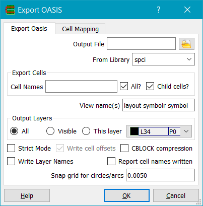
Choose a library to export OASIS from and the name of an output file which can be selected by using the file chooser button. If Strict Mode is checked, names of cells, text strings, layers, property names and property strings are collected together into tables and referenced by an offset in the END record as per the OASIS standard. In Strict mode, if Write cell offsets is checked, the property S_CELL_OFFSET is written for each cell in the cellname table so that random access to cells are possible allowing e.g. multithreaded reading of the OASIS file. If CBLOCK compression is checked, strict mode tables and cell data is compressed using RFC1951 compression. This can result in significant reductions in file size.
The View name(s) field allows you to specify what views are exported. The view names can be seperated by a comma or a space. They are populated by default from the views found in the library.
If cell name(s) are specified in the Output Cell(s) field and All? is unchecked, only the specified cells, and any of their child cells, will be output.
OASIS cells can be mapped from cellViews using cell mapping tab:
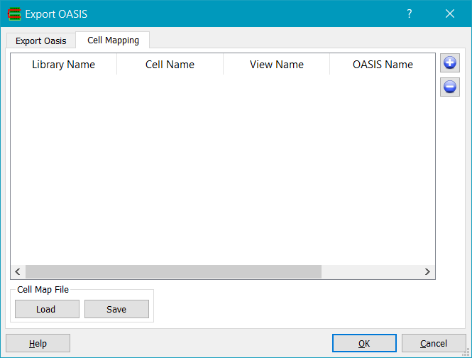
The + button adds an entry to the map table, the - button removed a selected entry. The OASIS Name field specifies the OASIS cellname, and the Library Name, Cell Name and View Name specify the cellView to map to this cell. The cell mapping can be loaded or saved to a file; the format is ascii and consists of 4 values per line (library name, cell name, view name and OASIS name) separated by whitespace. The same format is used by the cell map table in the File->Import->OASIS command. The map table is automatically populated with potentially conflicting cell/view names that would normally map to the same OASIS cellname. In this case each cell/view combination will have a map table entry, with an auto generated OASIS cellname which is of the form <cellname>_01, <cellname>_02 etc.
Selecting File->Export->LEF menu item displays the Export LEF dialog:
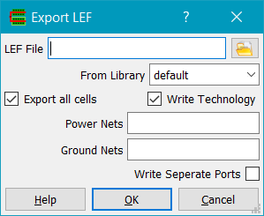
Specify the LEF file to export in the 'LEF file' field, using the file chooser button as required. You must specify the library to export from. Either all cells can be written, if Export all cells is checked, or just the currently open cell. If the Write Technology is checked, then the LEF technology section is written (layer widths/spacings, vias definitions etc). Power Nets specifies power pins in the LEF macros that should have their USE set to POWER. Ground Nets specifies ground pins in the LEF macros that should have their USE set to GROUND. Note that currently LEF technology section can only be written if a technology LEF has previously been imported.
Selecting the File->Export->DEF menu item displays the Export DEF dialog:
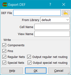
Specify the DEF file to export in the 'DEF file' field, using the file chooser button as required. you must specify the library to export from; however the library, cell name and view name will default to the current open cellview.
You may selectively write parts of the def file by checking or unchecking the Components, Pins, Regular and Special nets check boxes. For example DEF with just placement information would require just the Components and Pins checked. You can also choose to write just connectivity of nets, or the physical shapes as well.
Selecting the File->Export->Verilog menu item displays the Export Verilog dialog:
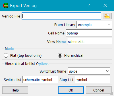
Specify the Verilog file to export in the Verilog file field, using the file chooser button if required. The library, cell name and view name fields are pre-seeded with the currently open cellview. Note that Verilog can only be exported from a cellview that has connectivity, e.g. one that was created by importing Verilog or DEF. If Mode is set to Flat, the Verilog netlist will be a flat representation of the top level design, else it will be hierarchical. For a hierarchical netlist from a schematic, the Switch List and Stop List control the netlist hierarchy traversal. Switch/Stop/Globals lists are stored with a name tag, so multiple different switch/stop lists can be chosen from. The SwitchList name field is the name of the tag. You can edit this name to create a new tag, and the name and the switch/stop/globals lists will be stored in the gladerc.xml file so they can be recalled in future sessions. The Switch List is a list of view names that the netlister can descend into. The Stop List is a list of views that the netlister will stop descending into.
Selecting File->Import->DXF... displays the Export DXF dialog:
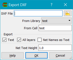
DXF is a common drafting format. DXF file specifies the name of the DXF file to export; the file can be chosen with the file browser button. The library and cell to export defaults to the current open cellview. If the cell contains hierarchy, subcells are also exported. If Export Text is checked, text labels are output to the DXF file. If All layers is checked, all the cell's layers are output; if not, only the currently visible layers will be output. Net Names as Text will output net names as text to the DXF file. Net Text Height sets the text label height.
Selecting File->Export->CDL... displays the Export CDL dialog:
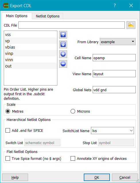
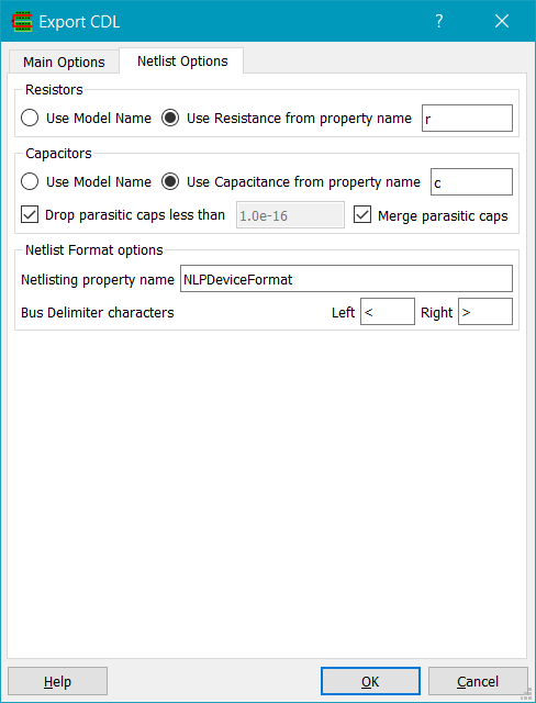
The Export CDL dialog can be used to write a flat netlist from a layout/extracted view, or a hierarchical netlist from a schematic view. CDL is a spice like netlist format with some extensions over spice syntax.
CDL file specifies the name of the CDL file to export; the file can be chosen with the
file browser button. The From Library, Cell Name and
The Pin Order List shows the order pins will be written in the extracted netlist .subckt header. This is so the user can match the pin order to a simulation testbench etc. For a flat netlist the pin order can be changed by clicking on a pin name and using the up/down arrow buttons to move the pin; pins are written in the order of the list from top to bottom. For a hierarchical netlist, the pin order is obtained from the NLPDeviceFormat property on the symbol view of the top level cellView.
Global Nets defines nets that should be global in the CDL netlist. They should be separated by a space character as delimiter.
Scale determines the scale of the units written to the CDL file.
For a hierarchical netlist from a schematic, the Switch List and Stop List control the netlist hierarchy traversal. Switch/Stop/Globals lists are stored with a name tag, so multiple different switch/stop lists can be chosen from. The SwitchList name field is the name of the tag. You can edit this name to create a new tag, and the name and the switch/stop/globals lists will be stored in the gladerc.xml file so they can be recalled in future sessions. The Switch List is a list of view names that the netlister can descend into. The Stop List is a list of views that the netlister will stop descending into, and instead write the device to the netlist according to its NLPDeviceFormat property. The Switch List and Stop List have no effect for layout view types.
Add .end for SPICE will add a .end line as the last line of the netlist, useful if you are netlisting a schematic for Spice simulation.
True Spice format will write the netlist in SPICE compatible format, with no $ arguments.
Annotate XY origins of devices annotates the XY coordinate of the device origin as $X=, $Y=.
For resistors, Use Model Name specifies that the resistor model name should be output to the CDL file instead of the resistor value. Use Resistance from property name specifies that the resistance, as given by the value of the property name, is output to the CDL file rather than the model name.
For capacitors, Use Model Name specifies that the capacitor model name should be output to the CDL file instead of the capacitorvalue. Use Capacitance from property name specifies that the capacitance, as given by the value of the property name, is output to the CDL file rather than the model name.
< If Drop parasitic caps less than is checked, all parasitic caps less than the specified value (in Farads) will not be output to the CDL file. If Merge parasitic caps is specified, multiple parasitics between two unique nets will be merged into a single lumped cap between the nets.
Netlisting property name is the name of a NLP expression property on the instance masters that will be used to control netlist formatting. It defaults to NLPDeviceFormat. If not present, the netlister will use a default suitable for Spice/CDL.
Bus Delimiter characters specifies the bus delimiter chancters used for buses.
Selecting File->Export->EDIF… displays the Export EDIF dialog.
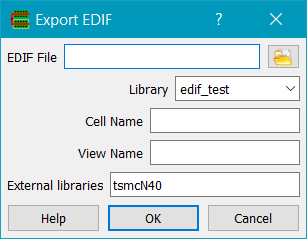
EDIF File specifies the file name to export to. Library , Cell Name and View Name set the design to export, which defaults to the open cellView. External libraries specifies reference libraries that will not be exported as libraries in EDIF, but as an external construct.
Selecting File->Export Image... dumps the current window to a PNG, JPEG or SVG format file.
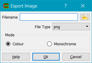
Filename specifies the file to export. File Type specifies the image type. PNG format is smaller and has superior image quality to JPEG, at least for layout data. SVG (Scalable Vector Format) can be scaled/zoomed without loss of image quality and is more suitable for schematics/symbols. Mode allows monochrome images to be exported, currently for SVG only. A monochome image may be preferred for documentation.
Prints the current design. The system printer options form is displayed allowing the user to specify paper size, landscape/portrait mode etc. The design is printed directly as it appears onscreen, so e.g. rulers etc. will be rendered. A white background should be chosen for printing on normal paper, and layer colours chosen carefully to give best results.

Reads Skill files written by dbWriteSkill in Cadence Virtuoso. Directory is the directory containing the Skill files to read. Use the Browse Folder button to select the directory; when done the directory is read and tech files for the various skill file libraries are created. The table lists the library name, the display file, the tech file and the regexp of the Skill file names. You can add or delete libraries as required. For example delelete the 'basic' library and cdsDefTechLib. Note that the Skill file parser is still in the experimental stage and does not pars all Cadence db... functions.
Reads a single Skill file written by Cadence Virtuoso.
Runs a python script. User python scripts will normally start with 'from ui import *' to import the database and gui wrappings. Python output is written to the Output dockable window.
Selecting File->Edit ascii file... opens a file chooser dialog and allows you to view and make simple edits to any ascii file.
Exits Glade. Any designs opened are checked for changes before exiting. If there are cells which have been edited, a list of the edited cells is displayed in the Save Cells dialog, with one dialog for each library containing unsaved cells.
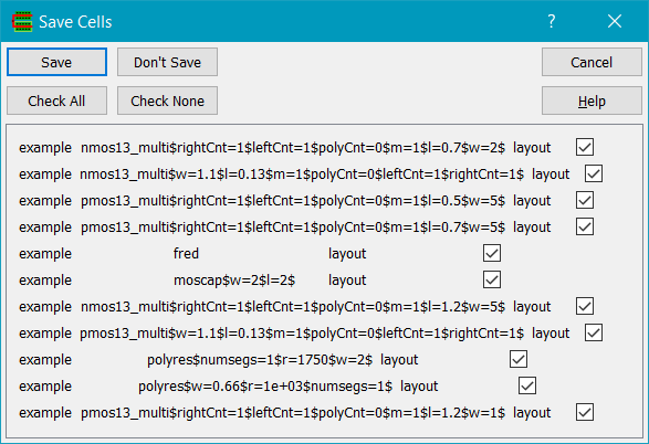
If Save is clicked, all checked cells are saved and the program exits. If Don't Save is clicked, no cells are saved and the program exits. If Cancel is clicked, no cells are saved and the program does not exit. If Check All is clicked, all the cells in the cell list are checked. If Check None is clicked, all the cells in the cell list are unchecked.
The Save Cells dialog is also displayed if the Glade window is closed via the window manager close button and there are edited cells that are unsaved, and may be displayed if a crash occurs and Glade is able to perform an orderly shutdown.
Copyright © Peardrop Design 2026.