Glade Reference
Follow the instructions in the README file in the installation package - it may help to set the GLADE_HOME and optionally the LD_LIBRARY_PATH and PYTHONPATH environment variables.
Start Glade either by clicking on the icon (Windows/Mac) or by typing glade at the command line (Unix / Linux).
Command line options
From the command line, Glade can be invoked with a number of command line options:
glade [-ng] [ -nobasic ] [-library libname ] [-libName libname [-tech techfile] [[-map gdsmapfile] -drf displayfile -tf cdstechfile] [-gds gdsfile ] | [[-gdsout_viewlist ] -gdsout gdsfile ] |[ [-oasisout_viewlist] -oasis oasisfile ] | [-oasisout oasisfile ] | [-dxf dxffile] | [-lef leffile -def deffile ] | [ -defout cellname deffile ] | [-edif ediffile ] [ -dspf dspffile ]] [-cell cellname] [-script pythonfile] [-h] [-v]
-ng: run in non-graphics mode. Note that this is really only meaningful with the -script option, and any python script must NOT call any gui functions e.g getEditCellView(), else an exception will occur.
-nobasic: Do not load the basic library automatically on startup.
-library <name> : a Glade library to open. If it does not already exist, it will be created. If the -library option is used, then options -libName, -tech, -gds, -oasis, -lef, -def, -dxf should not be used.
-libName <name> : a library name to import GDS2 or LEF/DEF into. If not specified, the library name will be 'default'.
-reflib <name> : a reference library. A subsequent -gds will use the library to resolve references in the GDS.
-tech <filename> : An optional Glade technology file to read. Technology files define layer colors, line and fill patterns and are described in section 2, Creating and using Technology Files.
-map <filename> : An optional GDS2 layer map file, used only when the -drf option is specified. It must be specified before -drf.
-drf <filename> : An optional Cadence display resource file. If specified, -tf must also be specified subsequently.
-tf <filename> : An optional Cadence technology file (ascii Skill format). If specified, -drf must also be specified first.
-gds <filename> : the name of a GDS2 file to import. Multiple GDS2 files can be specified.
-gdsout_viewlist <filename> : Set the export GDS switchlist, to pick which view is used for instance masters, in priority according to the order of the list. Must be specified before -gdsout. Default is "autoLayout abstract layout".
-gdsout <filename> : the name of a GDS2 file to export. The program will exit after the gds2 file is written.
-oasis <filename> : the name of an OASIS file to import. Multiple OASIS files can be specified.
-oasisout_viewlist <filename> : Set the export OASIS switchlist, to pick which view is used for instance masters, in priority according to the order of the list. Must be specified before -oasisout. Default is "autoLayout abstract layout".
-oasisout <filename> : the name of a OASIS file to export. The program will exit after the oasis file is written.
-lef <filename> : the name of a LEF file to import. Multiple LEF files can be imported, however duplicate definitions of SITEs and MACROs should be avoided as duplicate definitions will be ignored.
-def_view <viewname> : Set the name of the view to import DEF into. The default is "autoLayout". Must come before -def.
-defin_switchlist: Set the view switch list for resolving DEF instances. Instance views are picked in priority according to the order of the list. The default is "autoLayout abstract layout". Must come before -def.
-def_met_pins <true | false>: If set to true, pin text for DEF pins is generated on the pin metal layer; else it is on the system TEXT layer. Must come before -def. The default is "true".
-def <filename> : the name of a DEF file to import. A cell will be created according to the DEF DESIGN statement. Multiple DEF files can be specified.
-defout <cellname> <filename> : the name of a DEF file to export. The DEF for the specified cell will be exported.
-dxf <filename> : the name of a DXF file to import. The top level cell will be called 'top'.
-edif <filename> : the name of an EDIF file to import.
-dspf <filename> : the name of a DSPF file to import.
-cdl <filename> : the name of a CDL file to import. Cells will be created with a view type of 'netlist' for each subcircuit in the CDL/Spice file.
-cell <name> : the name of a cell to open and display. Note that the viewtype is assumed to be "layout".
-cellview <cellname> <viewname> : the name of a cell and a view to open and display.
-script <filename> : the name of an optional Python script file to run at startup.
-h: prints usage info
-v: prints the current version.
Stylesheet file
Glade will read a stylesheet file named glade.qss if found in the same directory as the executable. This can be used to e.g. set font size for the whole application, or for specific widgets. A guide to the file format is given in the Qt documentation.
Glade can read a Python startup file if it exists, and execute the Python commands in it before processing command line arguments. The startup file must be called .glade.py (note the preceding dot) and must be in your home directory - for Windows users the environment variable HOME must be set to this directory. For Linux/Unix/OSX users the home directory is '~'. A startup file is useful for loading e.g. a technology file, importing PCell libraries etc.
Glade manages design data in libraries. You can create as many libraries as you need. For example, if you have a number of GDS2 files, and want to use the design data in each in an overall top level design, you could import each GDS2 file into a unique library, then create a library to hold your top level cell which references cells from each of these libraries. A library is a collection of cells, where a cell is for example an inverter, a nand gate, a block or a complete top level design. Cells correspond to GDS2 STRUCT objects, or a DEF DESIGN, for example. A cell can have different views, a view being a representation of that cell. For example a view type of 'layout' is used to represent raw physical layout data e.g. the result of importing GDS2. A view type of 'abstract' is used for simplified layout data from importing LEF. A view type of 'extracted' is used when extracting layout connectivity and devices. The combination of a specific cell and a view for that cell is called a cellView. Views have a viewType, which determines which editor is used to open them. The viewType is specified when creating a cellView; an existing view's viewType can be set by right clicking on a view in the library browser.
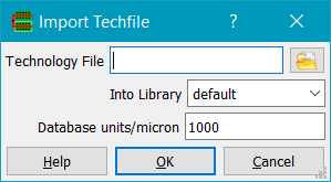
Before you can import design data, you need to create a library to hold that design data. You can use the New Library command for this, and then attach a technology file to the library using the Import Techfile command, or more simply just use the Import Techfile command, which allows you to enter a library name; the library will be created and the technology file attached to the library. As some people want to just read in a GDS file or LEF/DEF without bothering to create a technology file. the File->Import commands will generally allow you to create a library with a default technology file.
When Glade starts, the main window will be displayed and you are now ready to import design data. If you are not reading an existing library, it is a good idea to import a technology file, which defines layer colours and fill patterns. However if you don't have a techfile, you can still import design data; layers will be created with random colours and empty fill patterns. The layer names will be Lxxx where xxx is the GDS2 or OASIS layer number, or the LEF layer name if importing LEF. If importing an existing techfile, use the File->Techfile->Import menu command or the Ctrl+L bindkey.Specify the name of the technology file, or use the directory browser (button with folder icon) to select your technology file. You also need to specify a library name you with to read technology file info into. This can be any name.
Alternately, you can create a library using the File->New Lib command, which will allow you to specify the library name and techfile name (or no techfile).
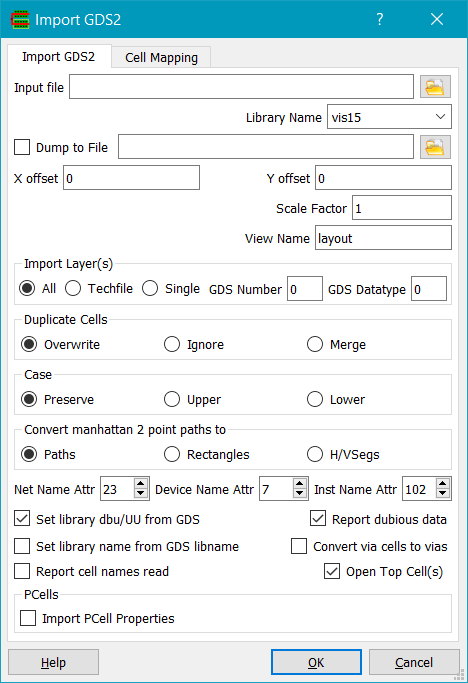
Next, read in the design data. For GDS2 data use the File->GDS2->Import GDS2 menu command or the Ctrl+I bindkey. This displays the Import GDS2 dialog. Enter your GDS2 file name as the input file, or use the directory browser (button with folder icon) to select a file. Other options on the form can be left as the defaults.
Alternatively you can import OASIS, DXF, EDIF, LEF and DEF or LEF and Verilog.
Once design data has been read in, you can then use the Open Cell (ctrl-O) command which displays the library browser to select cells to display. You can quickly navigate to a cell name by typing the first letter of the name, or use the Edit->Find... command in the library browser. Note that Glade always reads a library called 'basic' which resides in the distribution directory. The basic library is used for schematics and defines e.g. pins and power/ground symbols.
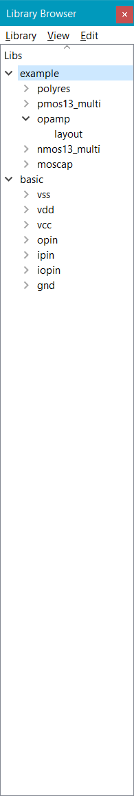
Open a cell by expanding the cell to show its views, then double click on the view. Alternatively right clicking on the view and selecting 'Open' from the popup menu can be used.
Once a cell is open, you can zoom and pan using menu commands, toolbar buttons, or zoom in using the right mouse button to zoom into a particular area by holding down the right mouse button and dragging from lower left to upper right. Right mouse dragging from upper left to lower right zooms out. Zooming in/out can also be achieved by scrolling the mouse wheel, if you have one. You can pan (move the viewed area of the design) by using the arrow keys, or by clicking and holding down the middle mouse button and dragging the mouse.
Objects can be selected using the left mouse button. Single clicking on an object will select one object, while holding down the left mouse button and dragging will select all objects enclosed by the drag area. Holding down the shift key while clicking on an object will add that object to the selected set; holding down the control key will remove the object from the selected set.
To control object selectability and visibility, use the layer select window (LSW) by choosing the Tools->LSW menu command. The LSW is then displayed.
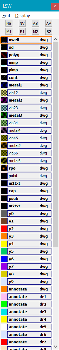
Each layer in the LSW has a colour box on the left, a layer name box in the centre, and a layer purpose box on the right. Left clicking on the colour box brings up the colour selection dialog which allows the layer's colour to be changed. Right clicking on the colour box displayed the stipple editor which allows the stipple pattern for the layer to be changed. Left clicking on the layer name box makes that layer the current drawing layer for 'Create' commands. Middle mouse clicking on the layer name box makes the layer unselectable, and grays out the layer name box. Right clicking on the layer name box makes the layer invisible, and grays out the colour box. Finally double clicking on the layer name box brings up a dialog which allows the layer name to be changed.
If you want to save your work to disk, use the Save Library command. This will save the design to a directory, with subdirectories for the cells in the library. Each cell directory has a further subdirectory for views of that cell, and in these the actual layout data is stored as a binary file. The library also stores the technology file information (layer names, colours, stipples etc).
Copyright © Peardrop Design 2026.